







Produkta tonis un faktiskā krāsa var atšķirties no attēlā redzamā, jo attēli ir ilustratīvi. Produkta apraksts ir vispārīgs un, iespējams, tajā nav iekļautas visas produkta īpašības.
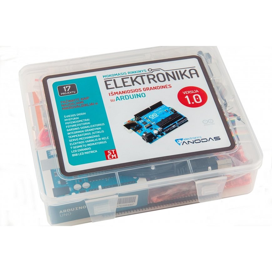
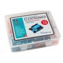
Anodas Electronics Educational Electronics Kit - Smart Circuits with ARDUINO
3665471 MOK1
4779044510139
Piegāde 8-12 d.d.
Viss par produktu
Introducing the electronics kit "Smart Circuits with Arduino ™ ". It contains everything you need to get acquainted with Arduino, electronics and programming. A journey through 17 smart circuits awaits you, after trying which you will be able to master the powers of the Arduino microcontroller, create interactive and fun projects. The kit contains all the necessary tools and electronic components. The kit book in Lithuanian will accompany you on your Arduino journey. The book contains information, step-by-step instructions, and diagrams presented in a vivid and clear language. Download the book.
"Smart Circuits with Arduino ™ " is an introduction to Arduino for everyone - beginners and advanced. Arduino is a small computer that enables you to control various electronic components and devices. Thanks to it, things come to life, execute our commands, and react to environmental changes. By assembling and testing the presented smart circuits, we will be able to consistently get acquainted with the possibilities of using the Arduino microcontroller:
GRND - 01. Start - Flashing LED
We will begin our acquaintance with Arduino by performing a very simple experiment, which is called blinking LED. In this experiment, we will make Arduino, greeting us, blink an LED. Yes, yes, you heard right, it will do this, because we have all the powers of this small but very powerful computer. With the simplest program, we will control the frequency of blinking of the light.
GRND - 02. Turning knobs – Potentiometers
In this experiment, we will work with a potentiometer. Potentiometers are usually used to adjust parameters such as volume or brightness. You will learn how to use a potentiometer to control the brightness of an LED with Arduino. The program demonstrates the operation of an analog input. Changing the position of the potentiometer knob will also change the blinking frequency of the LED .
GRND - 03. Colored light - RGB LED
A tricolor LED can glow in all the colors of the rainbow! Of course, this is much more interesting than a blinking LED. In fact, a tricolor LED is three LEDs (red, green and blue) in one housing. When we set various parameters of color brightness and intensity on the Arduino digital output, we get new colors.
GRND - 04. Dancing LEDs - More LEDs
Amazing. In the first lesson we learned how to blink an LED, in the third – a tri-color LED flashed in all the colors of the rainbow! It's time to complicate the circuit a bit and connect as many as eight LEDs to the Arduino. Also, using Arduino, various lighting effects will be created. We will make eight LEDs dance. The circuit is quite large and interesting. In this experiment, you will start creating your own programs and understand how Arduino works.
GRND - 05. Pressing buttons – Buttons
So far we have only done things with outputs. Now we are going to look at it from the other side and "play" with inputs. In this experiment, we will use buttons as sensors. This is the simplest and most obvious way to show how Arduino can receive information. Our condition is that if any of the buttons is pressed, the LED will light up, but if both buttons are pressed, the LED will not light up.
GRND - 06. When light falls – Photoresistor
In the second lesson, you learned how a potentiometer works, the resistance of which varies depending on the rotation of the handle - the stem. Now you will learn how to use a photoresistor, a semiconductor device as a sensor that changes its resistance depending on how much light falls on its surface. Using a photoresistor as a light sensor, we will control the brightness of an LED.
GRND - 07. Let's measure the temperature - Sensor TMP35
We will learn how to use a temperature sensor with Arduino. We will set the Arduino IDE debug window to display temperature changes. Using the "port display" (Serial Monitor), we will read the temperature sensor readings. TMP35 is a simple temperature sensor that changes its output voltage in proportion to the ambient temperature. They can be used for all kinds of automation tasks where temperature-dependent parameter changes are required. Transferring information from Arduino to computers is an even more interesting topic than previous experiments - we will start using the Arduino serial port. So far, we have limited ourselves to using simple diodes to display any changes. We will make sure that Arduino can not only signal changes in the environment, but, if necessary, easily communicate with a computer and display all kinds of text and data on any terminal.
GRND - 08. Turning the angle - Servo mechanism
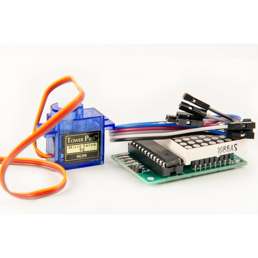
A servo mechanism, abbreviated as "servo", is a motor that consists of an electronic circuit with feedback. The "Servo.h" library has been created for Arduino, which can work with various types of servo motors. Servo motors are ideal for electronics and automation - they are characterized by high speed and the ability to accurately determine the desired position, which is not possible with conventional motors. They are quite easy to control using variable pulse duration. In this experiment, you will learn how to use PWM (pulse width modulation) to control a servo motor.
GRND - 09. When the music plays - Piezo buzzer
We're going to try to bridge the gap between the digital and analog worlds again. We're going to use a piezo buzzer that makes a small "click" when you briefly touch its contacts to a 5-volt power supply. Try this! Sure, it's not very exciting, but if you apply the voltage and then immediately remove it, and do it 100 times per second, the buzzer will start beeping. When you put hundreds of strings of tones together, you'll make music!
GRND - 10. Musical synthesizer - Connecting the potentiometer
Let's build a piezo synthesizer. We can use a piezo buzzer to generate sounds. It converts electrical frequencies into sound waves. Different sound waves are produced by rapidly switching a voltage (pulse) on and off. The program text processes two parameters that are read from two potentiometers. One potentiometer sets the pitch level, the other sets the duration of the repeating cycle.
GRND - 11. Turning the motor - Transistor and motor
Did you know about the servo motor we controlled with Arduino earlier? Now let's look at the rotation of a DC motor. This will require a transistor that can commutate (switch) a much higher current than the Arduino. When using a transistor, you need to make sure that its parameters are suitable for the particular equipment. The transistor we will use in this circuit, the TIP120, can handle 60 V and 200 mA, which is perfect for our motor!
GRND - 12. Let's turn on a larger load – Relays
Now we will learn how to control relays, giving Arduino more power! Rather, we will learn how to control a relay with Arduino. A relay is an electrically operated, mechanical switch. Inside the plastic housing is a powerful electromagnet. When it receives a charge of energy, the relay is triggered - the armature is attracted by the electromagnet and the contact group connects or disconnects the load power circuit.
GRND - 13. More dancing LEDs – Shift register 74HC595
Finally, we have reached integrated circuits (ICs). Now, using a shift register IC, we will control 8 outputs using only three Arduino pins. The 74HC595 shift register is an integrated circuit that has eight digital outputs. To use them, we will use a new interface called SPI (serial peripheral interface), which we will use to transfer data to the Arduino. One shift register will add 8 additional outputs to the Arduino and will occupy only three of its pins. We can connect a lot of such circuits. As a result, we will get a lot of additional conclusions, occupying the same three Arduino pins.
GRND - 14. Reborn Figures – 8x8 LED Module
In our next project, we will use a 64-LED matrix module as a display.
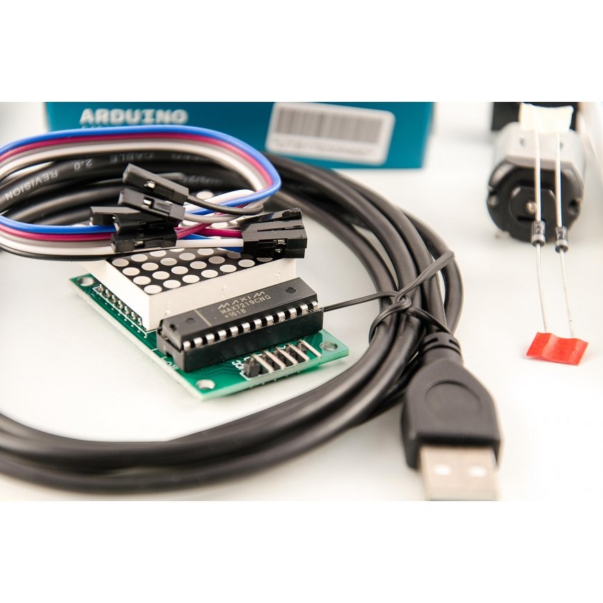
Since these modules use the MAX7219 integrated circuit as a controller, we will be able to turn each of the 64 LEDs on and off using only 3 pins of our Arduino. This is a simple and cheap way to control 64 LEDs and create a variety of animations. We can also connect several modules together to control even more LEDs. Our program will use the LedControl library. Download and upload it to the Arduino IDE: C:\Program Files (x86)\Arduino\libraries folder. Then restart the IDE software. Create more animations using the generator: http://www.pial.net/tools/ .
GRND - 15. Let's count - 7-segment indicator
The main advantage of LEDs is that, being small in size, some of them can be combined into a single small and compact package to form what is commonly called a 7-segment display. A 7-segment display consists of seven LEDs arranged in a rectangle in a specific order (see below). Each of the seven LEDs is called a segment. Different combinations of the seven segments being off and on allow the display of numerical values from 0 to 9. The location and pins (PINs) of each segment are marked with letters from A to G (see below). 7-segment LED displays come in two types: common anode and common cathode. The display with the number 5101AS printed on the side is a common cathode type display.
GRND - 16. Hello World - LCD Display
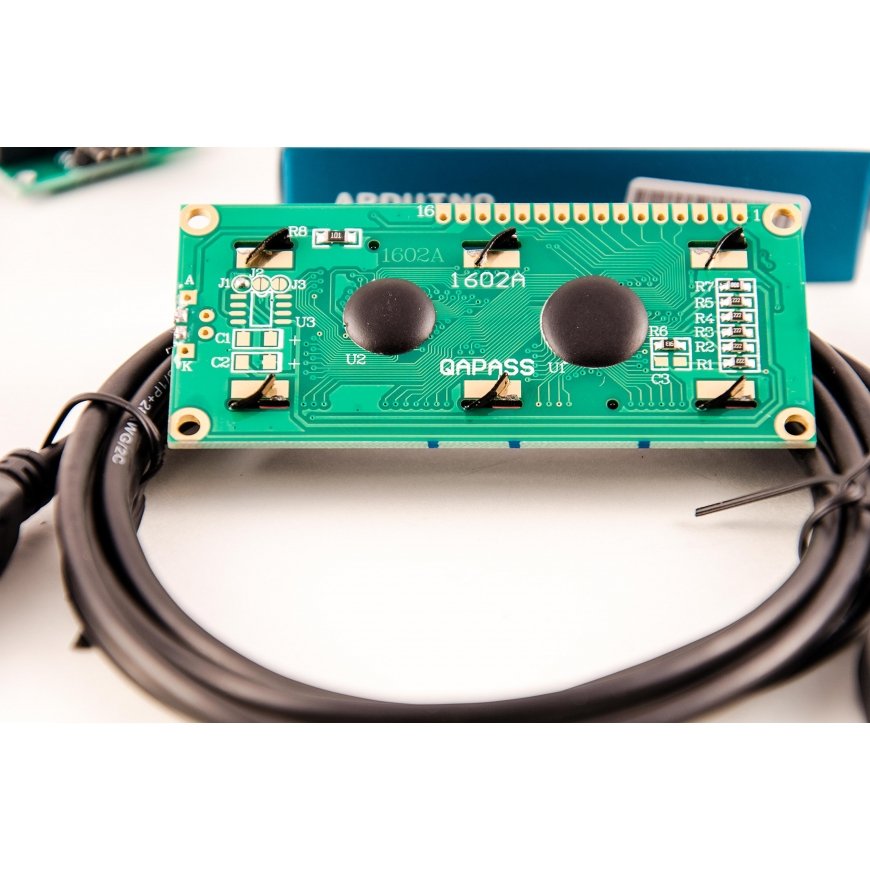
In this tutorial, we will learn how to connect an LCD to Arduino and display all the data on it. A Liquid Crystal Display (LCD) is a complex electronic module that we can use to display text or numeric data. The display is built into a PCB. It has two lines of 16 characters and is backlit for use in the dark. We used a Serial Monitor. You will see its similarity to an LCD and you will see that a large computer is not necessary.
GRND - 17. Let's Play – Reaction Game
Now that we have completed all the projects and learned all the basic terms of controlling components with Arduino, it is time to create something interesting. This circuit will show you how to create your own Simon Says game. With Arduino UNO, using LEDs, buttons, a buzzer, a few resistors, you can create this and other interesting games. How does it work? When we upload the code, the buzzer will beep several times and all four LEDs will start flashing. The game will start when we press any of the four buttons. Then a random LED will flash. You will need to quickly press the button associated with that color LED, thus repeating the pattern. If you guess it successfully, the pattern will be repeated again, only this time with another random LED added to it. The player must follow the pattern for as long as possible. With each successfully guessed pattern, an additional level of complexity will be added to the basic pattern.
Projects in the set:
- START - an introduction to how everything works.
- TURNING KNOBS - how to use a potentiometer to control LED brightness with Arduino.
- COLORED LIGHT – tricolor diodes, how to produce new colors.
- JUMPING LED - we will add more LEDs and make them jump with Arduino.
- WE PRESS BUTTONS - we will use the simplest sensor to transmit information to the Arduino.
- WHEN LIGHT IS ON – using a photoresistor as a light sensor, we will control the brightness of the LED.
- LET'S MEASURE THE TEMPERATURE - we will use a temperature sensor with Arduino.
- TURNING A CORNER – we will turn the servo using PWM (pulse width modulation).
- WHEN MUSIC PLAYS - we will create melodies with Arduino and play them.
- MUSICAL SYNTHESIZER – we will connect a potentiometer to the buzzer and create cosmic sounds.
- WE'RE TURNING THE MOTOR - we'll turn the motor with the help of a transistor.
- LET'S TURN ON A BIGGER LOAD - we will control the relays.
- MORE DANCE LEDS - Using a shift register IC, we will control 8 outputs using only three Arduino pins.
- REBORN FIGURES – we will create various figures using an 8x8 LED module.
- LET'S COUNT - when you need to output numbers.
- HELLO WORLD - we will connect an LCD to the Arduino and display all the data on it.
- WE PLAY – a reaction game where we combine everything into one.
Technical specification:
The kit includes an Arduino microcontroller, a breadboard, connecting wires, a USB cable for connecting the microcontroller, a power source connection cable, and more than 70 electronic components and devices.
Kit contents:
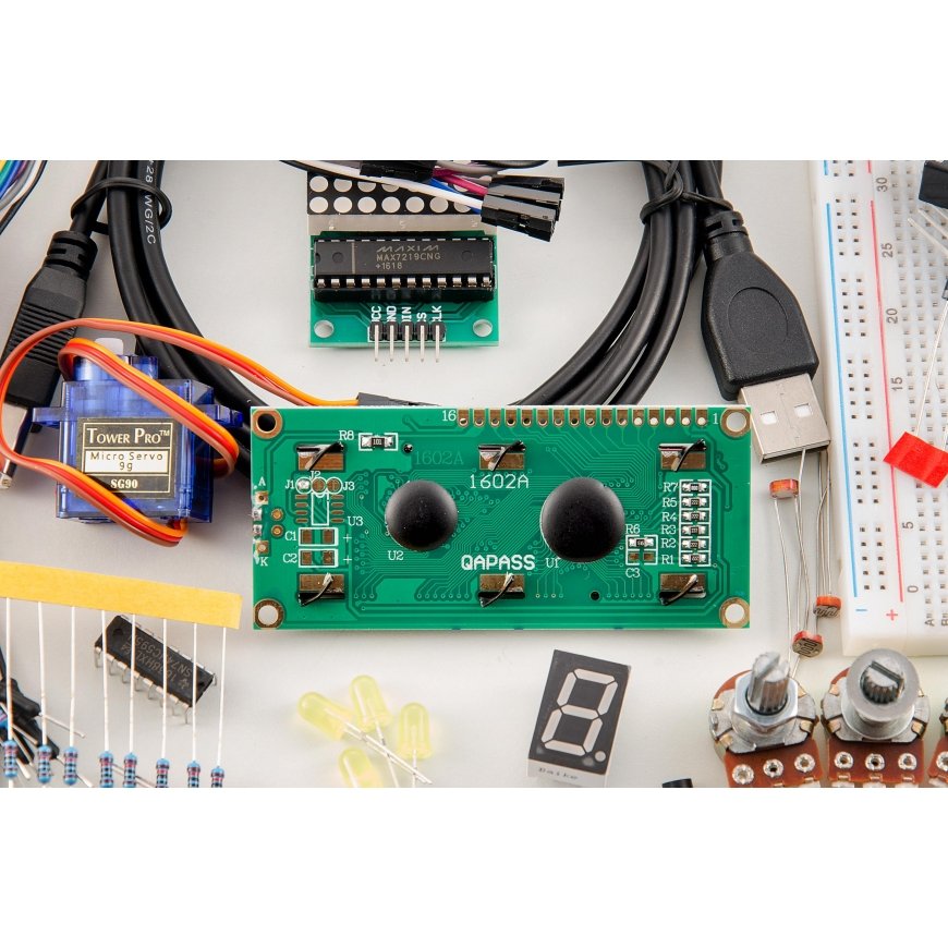
10x 220R resistor; 10x 1K resistor; 10x 10K resistor; 1x Potentiometer 10k; 2x Potentiometer 50k; 5x Red LEDs; 5x Yellow LEDs; 5x Green LEDs; 5x Blue LEDs; 1x RGB diode; 2x 1N4004 diode; 1x TIP120 NPN type transistor; 1x LM35 Temperature sensor; 3x Photoresistor; 4x Buttons; | 1x Mini-servo motor; 1x Buzzer; 1x DC electric motor; 1x Relay DPDT 5V-12A/125VAC; 1x 74HC59 shift register circuit; 2x 1-digit 7-segment module; 1x MAX7219 8x8 matrix module; 1x 16x2 LCD display; 1x Goldpin 1x40pin 2.54mm; 1x Arduino UNO R3 microcontroller; 1x Maxi layout plate (750 pcs.); 1x Breadboard wires (70pcs); 1x USB cable 1.8m; 1x Box; |
https://www.youtube.com/watch?v=KWuyn191d6U